Saturday, July 28, 2018

Day 181: Soundboard Down

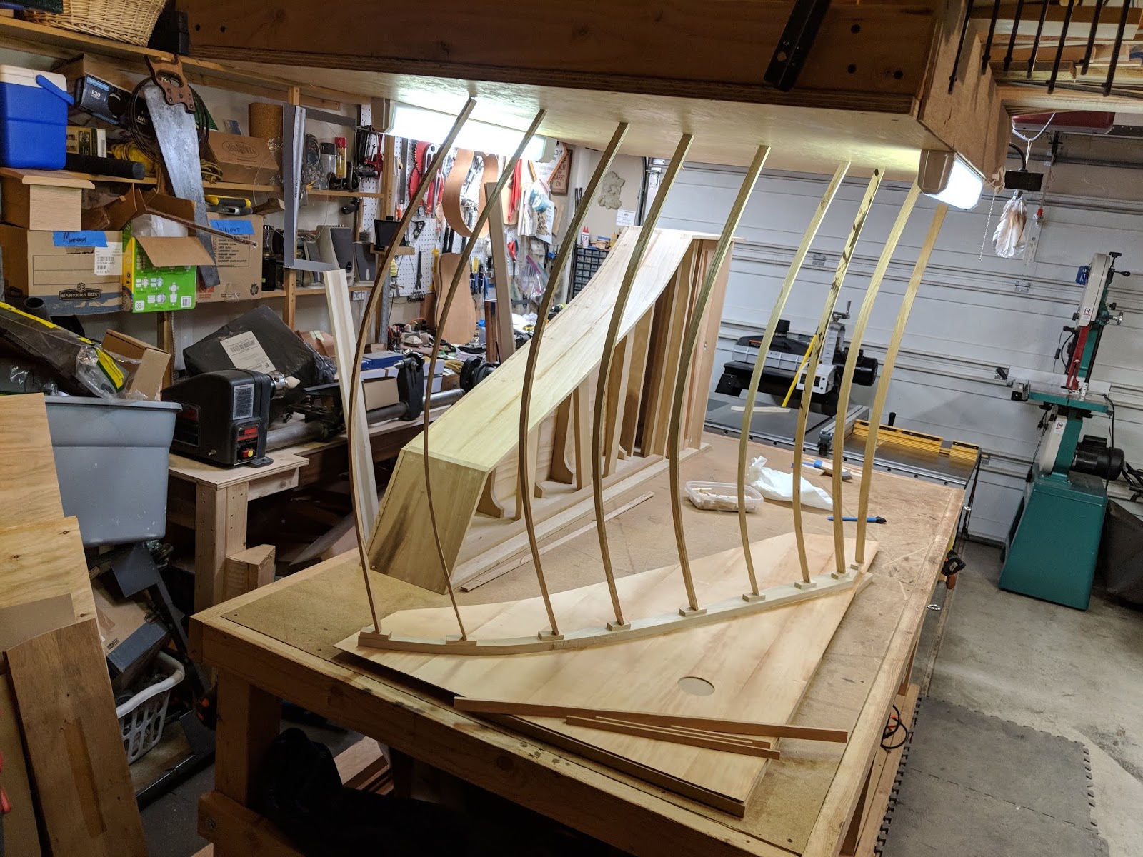
Before I could get the soundboard glued down, I had a couple of preparatory hoops I needed to jump through. First, Mr. Miller in his eBook Most Excellent describes how the four foot hitchpin rail (on the reverse side of the soundboard - this would make the top the obverse, but I digress) needs to bump up pretty snugly against the upper belly rail at the front of the instrument. After testing, I observed that it was off by about 1/2", so I cut up one of my gluing cauls (these lay on top of whatever you're gluing to provide protection for the wood under the clamp/go bar and to spread out the pressure laterally) and taped it onto the rail and tested for fit. It was pretty close, so I glued it up.


Close, but no cigar; it was still off by about 1/32". After having gone through the previous glued linen exercise with the cutoff bar and rib scallops, I realized a folded over piece of glued linen would just about cover the final space needed.


This thin addition made the fit, in a word, perfect.

The second step was to prepare the cauls and go bars. As I said above, cauls are small pieces of wood designed to protect the wood being glued up, as well as spread the clamping pressure horizontally. In this case, I'm using former go bars of ash that I had cut too thick. I also cut small divets into them with the band saw to more securely hold the go bars - probably not necessary, but helps me sleep at night.

What's a go bar, you ask? The go bar clamping system has been around for thousands of years. I suspect the Egyptians were using it. I've seen some nice draw-bore pegs in Egyptian chairs, so why not, right? Frankly, it was probably used long before that. The system is simple; it requires two fixed surfaces and a flexible bar to bend between the two. Here, I use the assembly table, a "go bar deck" mounted to the ceiling, and oak and maple bars. You want the bars to be thin, yet not too thin with a sturdy enough constitution to not break under pressure. Softer woods are not the preferred choice.


Once everything was sliced and diced to my exacting standards (good enough is good enough), I quickly ran glue around the liners and put the soundboard under go bar pressure. My secondary goal was to not glue the cauls to the soundboard - squeeze out has a way of doing that.


The next day, I pulled the bars and cauls and, voila!, a secure soundboard was in evidence. The nicest part of this is that I can now put the instrument on its spine and the soundboard doesn't fall out, a delightful consequence indeed.


Until next time...

Monday, July 23, 2018

Day 180: Putting the Soundboard in Reverse

Once I had the ribs cut and beveled into shape, it was time to redirect my attention to finishing up the bridges. A step I had not completed was cutting a final 10-degree-ish bevel into them. The result would be a fine ridge on their tops across which the strings will eventually cross on the way to their final termination points (i.e., hitchpins). But first, I needed to plug all of the placement holes in the 8' bridge with...yep, that's right...toothpicks.


Once I had all of the toothpicks placed and cut off, I scraped down the bridge and started beveling with a block plane. I had feared this step for months, yet it turned out to be easy work. I was done in no time, except for the hook - please do not tell anyone I used a Dremel tool to smooth out the bevel there. One interesting thing to note is how the toothpick at the end of the hook had entered a pitch pocket unbeknownst to me. It was hidden until I beveled it down. I decided to keep it because it's not hurting anything and how many harpsichords have a hook like that, right?


In the end, both bridges looked pretty great.


Once the beveling was done, it was time to get the bracing glued to the reverse side of the soundboard - you know, the side opposite of the top. But first, there was another step recommended by Owen Daly that made perfect sense to me: round the bottoms of the ribs and cutoff bar a bit so that clamping them on the ends will pull down the middle and create a slight bow in the top (a good thing). I clamped the No. 62 low-angle plane upside down in the bench and went to work.


Curving the ends was a breeze. I then decided that I would glue up the 4' hitchpin rail before proceeding further with the ribs and cutoff bar, so off I went.


While the rail glue was drying, I lined out the placement of the cutoff bar and ribs using a marking tool. The next day, I glued up the ribs, waiting to glue the cutoff bar down until I had scalloped the ends of the ribs.


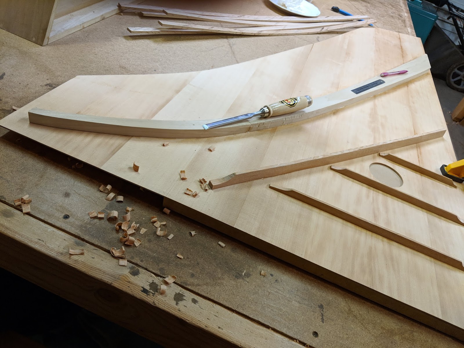
Then, on went the cutoff bar and its scalloping.


I keep my chisels razor-sharp, so everything went without a hitch. Owen also recommended I throw some linen soaked in animal glue onto the scallops as an extra measure. And also the Old Guys did this, so why not?


It's been in the 90s here and gluing with animal glues is always more easily accomplished in higher heat, so it's been something of a pleasure to work with the glue and get these final soundboard steps completed. The next step is to "close up the box" and get this thing headed toward completion. So far, things are looking pretty good (and, yeah, that's me in the last photo below).


Until next time...

Monday, July 9, 2018

Day 179: Making Some Delicious Ribs

Once the bridges were glued down and the rose hole cut, I could turn my attention to the back side of the soundboard; it requires five pieces:

1 - Cutoff bar
3 - Ribs of various sizes
1 - 4' hitchpin rail

The cutoff bar and ribs provide stabilization of the soundboard. Because I have a bit of a past in the guitar lutherie world, I just couldn't bring myself to make this bracing out of poplar and, following Owen Daly's recommendation, I procured a nice piece of CVG (close vertical grain) fir from Crosscut Hardwoods (paid $1 per pound) and cut all of the pieces with the quarter-sawn grain running down the sides.

As you probably know, I divested myself of my electric jointer a few months ago, choosing to rely instead on using a shooting board and the Veritas jointer plane to straigten board edges. In this case, I chose to create an index (flat) side using the table saw.


I do this by screwing a straight board to the plank I want to straighten and running an edge on the table saw. Of course, I posted about this on the Facebook project page and in the Woodworking Tips group where I received nearly no end of grief, especially with regard to my comment, which said, "We don't need no stinkin' jointer!" My favorite comment was the mansplainer who told me how ignorant I am for completely disregarding jointers and "everything they can do." Oh, boy.

Regardless of the interesting interactions, I was able to create the short edges and ran the board through the planer to complete its flattening. I'm not averse to using electric tools, I just don't have room for too many of them in my miniscule workspace. Someday, I'll have a larger shop and can tool back up accordingly. The results were great, so I charged forward.


I chose to cut the cutoff bar and ribs to dimension and then spokeshave them down by hand. Why did I do this? Mostly for safety reasons and because I just love doing handwork whenever possible/necessary.


No, the beer is not optional.


The bars are angled from top to bottom, just like the bracing on a guitar top and back. Now, I need to angle a few of the ends and get them glued to the soundboard. Once they're down, I'll get the ends scooped out (more to come on this) to create curved bevels.

On a tangential note, the days are beginning to heat up, which is actually a good thing for gluing when using animal protein glues that remain soluble longer at higher temperatures. This is the opposite of plastic glues such as Titebond, which like cooler temps in order to set up properly. So, while I usually take maintenance breaks during July and August, this year, I'll be gluing the bracing to the soundboard and getting the box closed up in the heat of Summer.

Until next time...

Tuesday, July 3, 2018

Day 178: Throwing Money Down a Soundhole

I've spent a pretty good chunk of change building out the shop, acquiring (the right) tools, and learning lessons far and wide. One of the best purchases I've made is the Shapeoko 3 XXL CNC machine. While it's largely a hobbyist's model, I love the darned thing. It fits perfectly in the shop and doesn't care which software I use to generate gcode to make it run. I use Autodesk Fusion 360 (for CAD/CAM) and two packages that came with the machine, Carbide Create and Carbide Motion, to also make designs and run the machine.

The worst thing about having a tool like a CNC machine is that it's a lot like a hammer - once you have a good one, everything starts looking like a nail. Fortunately, a CNC is not a one-stop answer for everything. In fact, it's quite limited in what it can for for me as I complete the instrument. Of course, as I learn more, that will change, but, for now, it helps me muddle through tasks that would otherwise be quite difficult to accomplish. Case in point: Cutting the rose hole into the soundboard.

I considered several ways to accomplish this. I thought about a hole saw, but had visions of the soundboard ripping to shreads under its marginally sharp teeth. Then, I thought I'd use the CNC and tried cutting the hole with an upcut router bit. A bit is defined partially by which way its spirals wrap around the bit when you hold it up by the end that is inserted into the router. If the spirals wrap to the right, it's an upcut bit; if they wrap to the left, it's a downcut bit. Some bits even have a combination of both.

An upcut bit drives the shavings and cut, as you would think, up toward the top of the cut. This is best when you want the bottom edge of the cut to be clean because this will leave a fuzzy top cut. When I tested an upcut bit, it left a fuzzy edge around the top circumference of the test material that was simply not acceptable. So, I headed to Lowe's and could only find a Dremel downcut bit, which didn't work too very well at all - it left steps in the cut, which is never a good thing. Eventually, I ordered a 1/4" downcut bit off of eBay and sat back to await its arrival.

In the meantime, Owen Daly recommended I visit him to observe how he cuts his soundholes using a circle cutter that fits into the drill press. I then remembered I had purchased one years ago and dug it out only to discover it was from that Harbor place and, basically, was a piece of junk. The test cut photos below attest to this.


The second one actually burned the wood. While I enjoy the scent of mahogany smoke as much as the next guy, it was not that pleasant this time around. I did a little research and realized I needed a better cutter, but, as with nearly every step of this project, life intruded and I was pulled away on other matters.

Until the downcut bit I ordered arrived. Then, the fun began.

The first thing I did was to run several test cuts on some cherry. Because the soundboard is roughly 3mm thick (less in some places), I set the cut pass depth at .5mm (which would require 6 passes based on the 3mm thickness of the soundboard) and let her rip.


I was quite pleased with the quality of the cut - no fuzz whatsoever - so I set the soundboard up on the CNC, held my breath, and went for it.


The result was a perfectly cut hole with a diameter of 69mm.


I shared a photo of the cut with a friend who owns a large CNC and he said, "That's one expensive circle." My reply: "Yeah, I just threw $1500 down a soundhole." Rest assured, I'll keep at it so I can amortize the cost of the machine into other cuts. Besides, it's really kinda fun.

Until next time...

Monday, June 25, 2018

Day 177: Deja Vu All Over Again

After the sizing episode, it was time to start gluing stuff to the soundboard. I started by lining out where the bridges and four foot end pins would go using a marking tool and punch.


Then, I threw some glue on the eight foot bridge and proceeded to get it down. I cut the heads off a few nails and used them as guides inserted into the existing holes. Once the go bars were in place, I removed the nails.


A word about go bars: This is an ancient method of clamping (or cramping for my friends in the United Kingdom) that probably goes back to the Egyptians, if not earlier. It simply uses the tensile strength of thin pieces of hardwood to bind whatever you're gluing to whatever is receiving it. In this case, it's all about pushing the bridges into the soundboard.

After 24 hours, I removed the go bars for inspection and all was well.


I then proceeded with the four footer, only there was a small hiccup - the damned thing snapped while I was bending it into position on the plan that was laid over the soundboard. Rather than become upset, I simply cut, bent, spokeshaved, and glued up a new one. All steps were completed within 48 hours. Easy peasy. So easy, in fact, I'm thinking about changing the company name to Tortuga Early Instruments Harpsichord Bridge Company.


Now that the bridges are in place, I need to cut out the sound hole (especially before I start gluing things to the back of the soundboard). I'm not going to disclose how I'm cutting it at this time, though I'll throw you a hint: Clean No Cars.

On a couple of tangentially related notes, I acquired a nice holly log from a woodworking friend. Thanks, Kate!


Like the PEEK from Robert Webster, I now have enough holly to make jack tongues for the rest of my days on the planet.

Another generous friend, Geir Bremnes, sent me drawings he has made of an I. Ruckers 1640 single manual that resides at the Rijksmuseum in Amsterdam. He's one of the kindest people I know and has asked me to pay it forward as a way to repay him for his generosity.


I'll be posting more about this instrument in the days ahead. Thanks again, Geir!

Until next time...

Thursday, June 14, 2018

Day 176: Curling for Fun and Profit

Once I settled on the locations of the bridges on the soundboard, I could go ahead and make some more drastic measures to get things into place. For instance, the best way to position the bridges into the soundboard is to drill holes into them and nail them to, say, a piece of plywood under the soundboard.


As you may recall from my last post, I positioned the bridges according to their original locations on the R.K. Lee drawing of the 1640 as it currently sits in the Yale Collection of Musical Instruments. It was fairly nerve-wracking driving nails into my beautiful, pristine soundboard, but it was required, so there you go. And I did likewise with the 4' hitchpin rail, which will be mounted on the reverse.


More than anything, these become positional guides during glue-up, which will happen this weekend.

Another interesting aspect of soundboard preparation is the application of "sizing". Size is simply diluted glue. In this case, it's diluted glue made from animal protein in an 11:1 water to glue ratio. Sizing is typically used for later gluing because it will soak up and guide full-strength glue during a gluing session. In this case, it's intended to tighten up the soundboard, enhancing it's tonal qualities.

Now, the really interesting aspect of this exercise is the curling it produces on the incredibly thin (2-3mm) jointed piece. The top did not produce much curling (this is probably a photo from after it had settled down a bit).


The back was another matter entirely.


As I like to say, "Oh, boy." As nerve-wracking as driving nails into the precious thing was, watching it curl like this put my teeth on edge, so I stepped out of the shop for a couple of hours. When I returned, this is what I saw:


Whew. The little fella had settled down considerably and I could breath much, much easier. Of course, this is what Owen Daly said would happen. I trust him completely, but it was still interesting to observe.

Another aspect of the sounboard is the apparent discoloration. The photo of the top was taken while it was still pretty wet with the size. When it's dry, it maintains a consistent cream color. This was intentional. When I purchased the wood, it was in a stack of "piano wood" that had been sitting in a retail space for the better part of 15 years. This resulted in the outside of the wood darkening a bit. I purposely put the darker sides on the reverse. Once the soundboard receives the bridges and a little paint, all will be well.

Until next time...

Monday, June 4, 2018

Day 175: In the Green

After input from master builder, Owen Daly, and much research and deliberation, I believe I've come up with the proper placement trajectory for the bridges. This all began when Owen noticed something might be a little off with the placement of the bridges that would affect the ultimate tone of the instrument. In the absence of having specs on the original instrument this copy represents (the A. Ruckers 1640 single at the Yale Museum), I found string speaking lengths in "the O'Brien book" for an A. Ruckers 1637 single and recorded them (see table below).

Now, the instrument in Ernie's eBook Most Excellent represents a ravalement (later alteration) of the instrument, making it wider, which I believe would affect the placement of the bridges. Yet, I had a nagging suspicion I would want to stick with the original placements. This presented a secondary problem: I didn't have a drawing or any detailed information on the original instrument.

This is when Owen came to the rescue by loaning me his copy of the drawing done by R.K. Lee in 1971 of the original instrument at Yale.


This was a revelation. Based on the drawing, I created a spreadsheet comparing the 8' and 4' string speaking lengths (typically done for all Cs and Fs as a quick gauge) using all the data I had at that time. All measurements are in millimeters.

8’ Miller 1640 Yale 1637 AR* 4’ Miller 1640 Yale 1637 AR*
c''' 171.5 169.5 171 c''' 89 80 83
f'' 257.5 259.5 258 f'' 132.5 126 129
c'' 331.3 345 348 c'' 174.5 169.5 173
f'  485.5 512 531 f'  253.5 245 258
c' 623.5 677 698 c' 332 324 338
f 884.5 927 963 f 450.5 450 474
c 1073 1111.5 1165 c 544 545 580
F 1320          1368 1351 F 695 697 717
C  1393.5          1409 1366 C 800.5 787.5 736
*Germanisches Nationalmuseum, Nuremberg, No. MIR 1073

As you can see, the figures in the tenor and at the hook vary a bit, yet all of the Yale 1640 figures are either very close or nearly the mean between Miller's copy and the 1637, especially with regard to the 8' numbers.

At this point, I marked out the 1637 and 1640 pins on the Miller plan. The orange marks represent the 1637 and the green represent the Yale 1640.


I now must make a decision: Do I follow the Yale green points or Mr. Miller's CAD drawing? Interestingly, when I laid the bridges onto the R.K. Lee drawing, they were a nearly perfect fit to the Yale 1640 marks with little final bending during glue-up required.


My inclination is to follow the green marks wherever they may lead. Regardless of my decision, the bridges will be glued down this week. Finally.

Until next time...