Sunday, June 26, 2016

Day 121: Hide Glue and Holes

The last time we spoke, I was working on both the harpsichord and the Roubo-style bench. Nothing has changed, except the amount of progress I've made. As you may recall, I discovered a hinky angle on the spine side of the tail. Well, I checked the template I used to make the cut and it was spot-on. I shall console myself with the knowledge that some things in this life must remain a mystery. Regardless, I cleaned up the angle and am now ready to glue the sides to the bottom.


Speaking of glue, after conferring yet again with Owen Daly of Owen Daly Early Keyboard Instruments, I decided to wait until I got my hot hide glue act together before proceeding. While conversing with Owen, he offered to sell me some of his 192-gram dried glue. Hide glue comes in several gram strengths and 192 seems to be ubiquitous among luthiers of all stripes.


I also purchased a hot pot on recommendation from Jan van Capelle, the Dutch Luthier. Not only is Jan a master luthier, he's a master at saving money, which I like. A lot. This setup reminds me of my bending tool that consists of galvanized pipe and a heat gun that I put together for around $30. In this case, I'll be mixing equal parts glue granules and distilled water and heating them in a glass jar immersed in water in the hot pot. I'll cook it to around 140 degrees Fahrenheit and let it cool down overnight. Then, I'll bring it to heat once again right before using it.

The plastic container with the label in the photo above is urea, a substance that will provide longer open time when I use the glue. Open time is the time it takes for the glue to set up. Hide glue is notoriously fast at setting up once it begins to cool to room temperature. Urea helps prevent this and can even make the glue more pliable for joints that will be under the strain of wood movement. Some builders also use salt for a similar purpose and the jury is still out regarding how much urea and/or salt affect the strength of the glue.

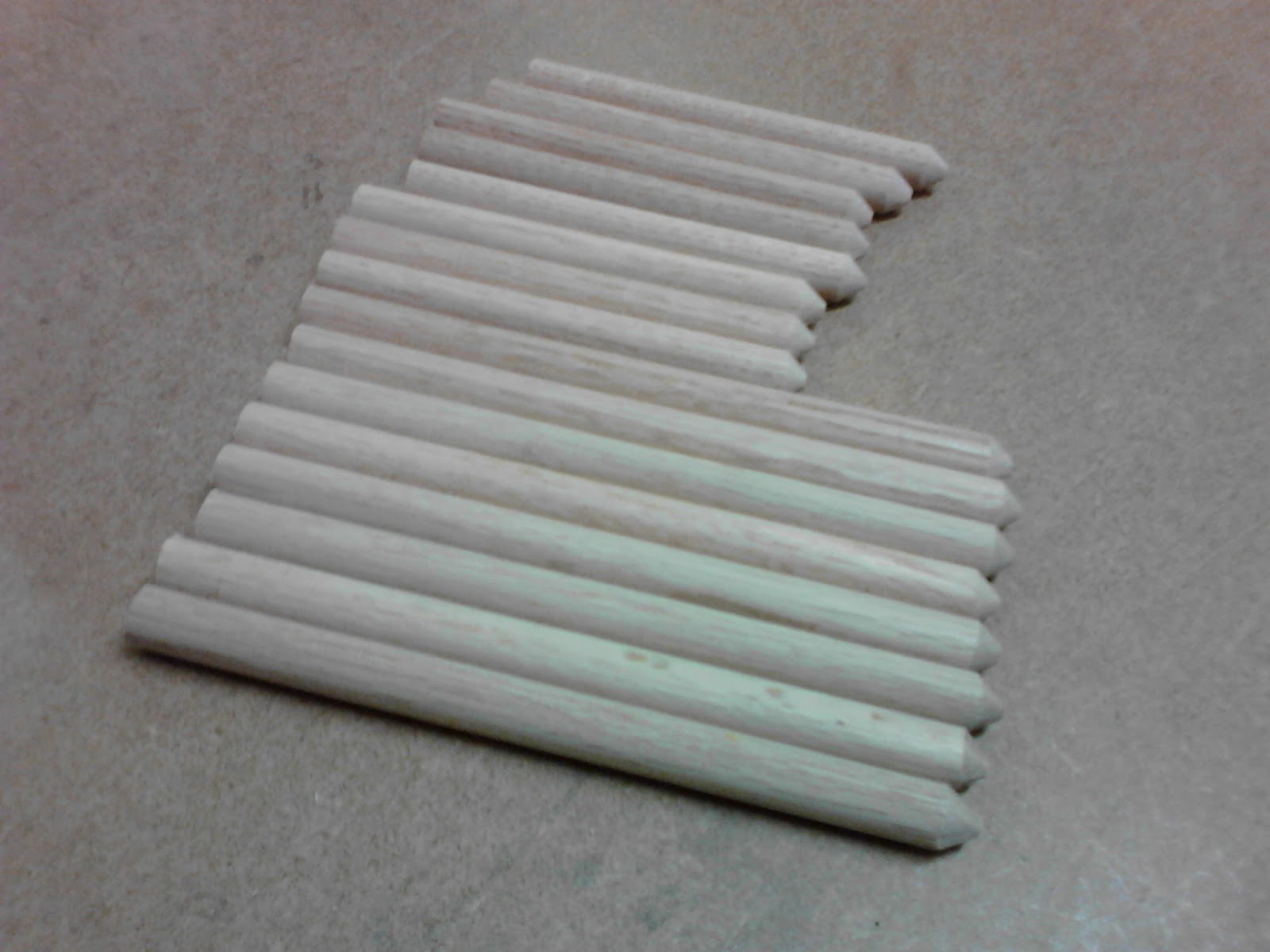
So, I've decided not to go with screws and yellow glue as mostly recommended by Mr. Miller in his eBook Most Excellent. I've decided to use trenails (square pegs) driven into holes that are smaller than the pegs. This creates a bond that, as Owen is wont to say, "holds like grim death." Of course, I'm going to test this method out first, but I must admit it seems intuitively to be more aligned with the quality of instruments I want to make. This is no judgment about Mr. Miller's methods at all, only that I think I prefer this method at this time. We'll see.

On a somewhat related note, I was able to complete the tail vise for the workbench this weekend. After cutting some walnut to dimension (yeah, the free stuff from Goby Walnut and Western Hardwoods), I stopped to sleep on how to go about drawing routing lines and screw holes into the bench side piece. Fortunately, I dreamed (literally) up a solution using parchment paper from the kitchen to make a drill template.


You can see where I routed out the walnut board and finished it with Tru-Oil. Because the vise was mounted to the bench, I had no idea how to place the holes with complete accuracy. As I said, I dreamed about using paper of some sort to draw everything out, which made it super-easy to accomplish the task.


Once I got the holes drilled and countersunk, I mounted the piece to the bench.


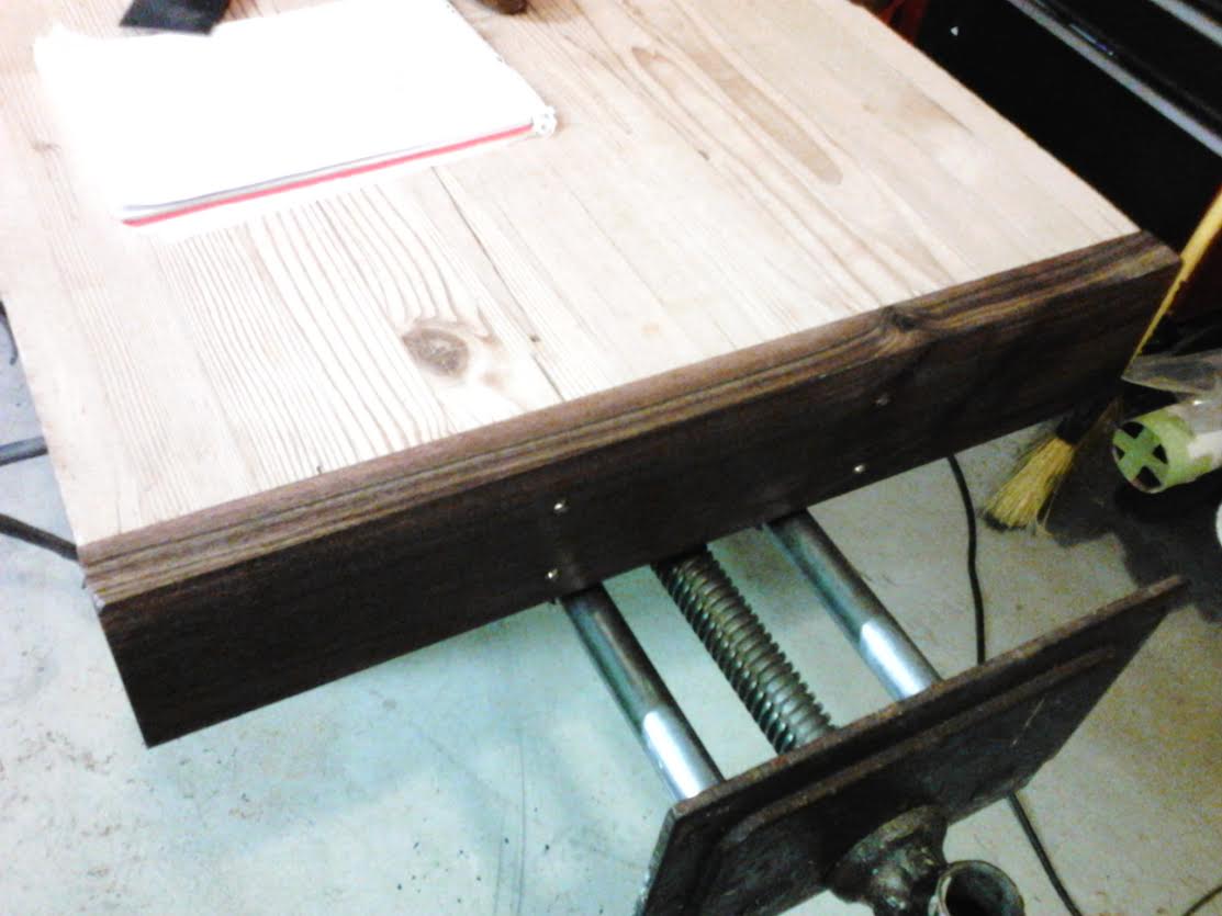
Then, I simply mounted the other piece by putting it in the vise and closing the contraption. I drilled the holes and put in the screws with the vise shut and, voila, it was suddenly finished.


I didn't document this fully because, well, it was a pretty boring process, but you get the drift. This vise is an antique 10" quick-release model my wife purchased for me as a birthday present from Astoria Vintage Hardware during one of our monthly pilgrimages to that fair city. I think it's going to work out fine and I'm glad to have this part of the project completed. Next, I'll add a few dog holes to the distal side of the tail vise, trim back the leg mortises (they're 1/4" rich above the bench top) and begin the exacting process of completing the leg vise, which will allow me to call the project completed.

Until next time...

Tuesday, June 21, 2016

Day 120: Assembling the Case

Once I got the spine and cheek glued to the nameboard, pinblock and lower belly rail, I could begin the process of gluing that structure and the bentside and tail to the bottom. Ruckers (i.e., Flemish) harpsichords are built "on the bottom," which means I will be gluing the sides to the bottom. But first, I needed to dry fit all parts by drilling lots and lots of holes in the bottom.


This is in keeping with Mr. Miller's directions in his eBook Most Excellent. I did talk things over with Owen Daly of Owen Daly Early Keyboard Instruments and decided to continue to follow Mr. Miller's directions. The next instrument will likely be a little Italian, so I'm just going to meander along the trail following Mr. Miller until the end. Besides, this one is mine, so I don't have to worry about the added level of scrutiny under which the pros regularly toil.

Once I got the hundred or so holes drilled, I began the task of clamping the sides onto the bottom and securing them with 1 1/4" (#8) screws.


Things were going well until I clamped on the tail only to discover the angle I had cut is not going to fit.


I suppose this is why Mr. Miller recommends a dry fit before the final glue-up. Thanks again, Ernie. I'll have the angle recut and everything screwed in by the end of this week.

On a tangentially-related note, I'm still working on getting the Roubo-style bench wrapped up. As much as I'm loathe to admit it, Random Roger Green has several interests outside of completing my bench, so we've been on a bit of a short hiatus. Once he has time to reengage, we will be trimming up the leg vise chop for final mounting and drilling the dog holes into the top. Until then, I'll be working on mounting the end vise. As you can see in the photo below, I'm using some of the walnut I scavenged from the Goby Walnut and Western Hardwoods free boxes.


I started by planing them down and then cutting them to size.


When I mount the vise, I'll provide greater detail about that process. My intent is to mount it directly to the bench top and route out the walnut to fit the vise (as opposed to doing any more routing of the bench top). I'll also have this knocked out this week.

Until next time...

Sunday, June 12, 2016

Day 119: Nameboard Installed

Now that I've jumped back onto the instrument - building the instrument, not actually jumping on it - I'm working on both it and the Roubo-style bench at the same time. The most recent instrument glue-up was the nameboard. I will eventually inlay a nice Tortuga logo of some sort into it, but, in the interest of time, I felt the nameboard needed to go on sooner, rather than later, especially since Mr. Miller recommends it in his eBook Most Excellent - and I always follow Mr. Miller's directions. Will I regret it? Only time will tell.


I also got the pinblock (aka wrestplank) support blocks installed. No issues there whatsoever.


Once the supports and nameboard were glued up, I went back to the bench - there's still a lot to do there.

Because Random Roger Green and his buddy, Dave Legg, said they would help me get the workbench legs put together and the top on, I went ahead and cut and rounded some drawbore pegs with great anticipation. Drawboring is an ancient woodworking technique. In fact, Random told me he observed drawbore pegs in the legs of more than one chair in the Tutankhamen collection. I suspect it was used long before Tut's time, as well.

Drawboring is intended to be used with mortise-and-tenon joints like those between the workbench legs and stretchers (the small planks that will hold the shelf near the bottom of the bench). The technique involves drilling holes into the mortises, pushing in the tenons, marking the holes, removing the tenons, remarking the holes closer to the proximal part of the tenon and drilling them there. Then, pegs the size of the drilled holes are hammered into them, drawing them in for a super-tight fit that will last, well, for millennia.


All the rounded points need to do is pick up the adjusted hole in the tenon. In this case, we moved them 1/16", which made for a nice, tight fit, indeed.

When Random and Dave showed up, we got to work right away. The first thing we did was to prepare and dry fit the legs to ensure a successful gluing session later.


All went well, so we threw down some plastic and glued it up using Garrett Wade Gap Filling Glue.


Next, we put the leg structure on the floor and gingerly pounded to top into place.


Alas, we neglected to dry fit the top and ended up putting it on backwards! This was pretty demoralizing (for me, for Random and Dave, not so much - they have a lot more experience than I and knew it could be fixed), so we called it a night. A couple of days later, I devised a plan using a floor jack, some scrap wood and patience and, voila!, I was able to pop off the top, turn the legs around, and pound it home again (with the help of my neighbor, Mike Crane - a Renaissance man who is a general contractor, master woodworker, expert metalworker, and journeyman body-and-fender man - and my hero).


The clamp in the photo above is holding a split together where I squeezed in some glue. Once things had set up overnight, I flush cut the drawbore pegs (1/2" dowel from Home Depot).


At this point, I was pretty happy with my progress, so I went ahead and test fitted the leg vise chop just to see if things lined up and if the crisscross worked as intended.


Not too shabby. The chop itself still needs some trimming and shaping, which I will do at Random's enormous shop over the next couple of weeks.

I then pulled the chop off and turned my attention to the deadman. What's a deadman? It's a vertical board with strategically spaced dog holes. What's a dog? It's simply a spring-loaded peg used during clamping. In the case of a deadman, a dog is used to balance a board of any length that may find itself locked in the jaws of the leg vise. The first step in the process was to build a raised track along which the deadman glides.


You may also recall from a previous post that Random and I cut a 1 1/2" x 1" trough under the front of the top. This trough acts as an upper retaining guide for the deadman top. You'll see what I mean in a moment. Back to the rail - it's a little thinner than the front stretcher and 1/2" high with a 1/2" flat space at its peak. As you can imagine, this means I needed to cut a complementary negative space into the bottom of the chop. So...that's what I did.

But before I started cutting, I drew as much onto the face of the deadman as I could. The deadman is made from the same 8/4 piece of alder I used to cut the stretchers. And, yes, that's the lid from a seafood boil pot I'm using to make the cut curves in the photo below.


Now, in my zeal to route the top of the deadman to fit in the bench top trough, I cut it in the wrong place, hence the appearance of the "unforeseen artistic embellishment" using some of the walnut I had scavenged from Goby Walnut and Western Hardwoods. I thought it would look okay with the darker strip at the top. Unfortunately, it kind of looks like crap, but, frankly, I don't care. As Random is wont to say, "It's just a bench."

I then laid out  the dog hole locations and went to work on the drill press with a 3/4" Forstner bit.


You will also notice another creative "unforeseen artistic embellishment" at the top of the deadman in the photo below. As I was routing out the piece that sits in the trough, the router chipped out a large chunk. Rather than ditch the nice, big piece of alder, I simply sanded another small curve into it using the Rigid oscillating spindle sander.


As always, everything worked out in the end. The deadman glides quietly along its little track and I can't wait to start using it to finish up the harpsichord.

Until next time (when I dry fit the case to the bottom and start gluing up the sides)...

Wednesday, June 8, 2016

Day 118: Back to the Reason for the Season

Well, the Roubo-style workbench is finally wrapping up. I'll have the thing completed over the next couple of weeks. Random Roger Green has been generous with his time and tools and the insights he's given me not just about the bench project, but woodworking in general, will continue to prove useful to me for the rest of my days. Thanks again, Roger - you're a gentleman and a scholar.

This past week, Random and I worked on test fitting the legs. As expected, there were a few challenges that were handled with some joinery float work. I must admit that it was a bit tedious jamming the legs in and then using a clamp to push them back out, but it was a necessary exercise. And Random did most of the heavy lifting. Literally.


The process was to jam a leg in until it would jam no farther, pull it out, observe any shiny areas under proper light, and shave the tenon with a float to remove the obstruction. This also went for the mortises where I shaved a bit off using a float, as well. The result of this hard work is a bench ready for top, leg, and leg stretcher assembly. We'll be using the drawboring technique, which I will explain in detail later this week.

On a completely unrelated, totally salient and exciting note, given the state of the workbench, I decided to jump back onto completing the instrument - the point of the workbench exercise and this blog. If you found my workbench posts boring, my apologies. I simply considered them an important part of my build process, one that often requires me to take two steps back after having taking a good, solid three forward. I'm still building out the shop for harpsichord making and posting about go-bar decks and assembly tables and workbenches is part of my effort at being completely transparent about my work.

As you may know, I'm following the detailed directions carefully laid out in Ernest Miller's Harpsichord Project E-book 3.1. It's highly unlikely I would have embarked upon this project without Mr. Miller's book and I'm grateful every day that he took the time and effort to create it - and that I was able to find it on the interwebs.

The first step in reacquainting myself with the project was to review the parts and pieces I had previously cut. To review: I found I had prepared the bottom, spine, cheek, bentside, tail, lower belly rail and pinblock. Considering these parts, I went back to Mr. Miller's eBook Most Excellent and saw that it was time for me to cut a couple of pinblock support blocks out of some of the red oak I had on hand.


Once the pinblocks were cut and drilled to satisfaction, I grabbed the bottom to lay it down so I could review the fits of the case sides and found that the keybed section had begun to separate from the rest. This was not good and, frankly, I don't believe I would have discovered this had I not taken the long, unforeseen break to build the workbench. I quickly remedied the situation with some Garrett Wade Gap Filling Glue.


I'm honestly not sure what this speaks to. Was it my lack of woodworking experience or my typical haste that caused this problem? Regardless, it's a learning opportunity that I don't take lightly. This sort of thing is completely unacceptable and I'll be more careful with my jointing in the future.

Once I fixed the bottom joint, the next step in Mr. Miller's eBook Most Excellent was to glue the pinblock to the case sides. I had already routed the sides and test fitted them a few months ago, so I was confident everything would go together nicely.


I must admit one concern: the lack of tuning pin holes in the pinblock before glue-up. I would much rather have preferred drilling these on the drill press before the glue-up, but I've learned that deviating from Mr. Miller's directions is a cause for disaster (see my tail comments below). The next step was to glue up the lower belly rail, so I flipped the structure over and went to town.


Things were going nicely until I got to Mr. Miller's instructions about cutting the tail to length and setting its end bevels to match the spine and bentside. In my infinite wisdom, I had charged ahead months ago with the tail sizing and bevels - without following Mr. Miller's directions. The result: a tail that was too short - it met up with the inside of the bentside outline on the bottom, rather than the outside of the outline. Once again, I proceeded where I saw fit and the outcome was a tail that simply could not be used.


It looked great, but I believe the reason it must be on the outside of the spine and bentside lines is to act as support for the ends. This is important when the strings begin to pull on the case. I then recut the tail to the proper dimensions (following Mr. Miller's directions) and realized I could save the useless tail to act as a table saw angle template for future instruments - should I make another one based on Mr. Miller's plans.You can see in the lower right of the photo below where the tail terminates on the outside, not inside, line on the bottom.


It's a great feeling to be back to work on the instrument. The workbench may have chopped 90 days out of the instrument build timeline, but it will be worth it in the long run to have a perfect bench for hand planing, etc. For now, I'm enjoying the process of creation once again.

Until next time...

Saturday, June 4, 2016

Project Update: Finishing Up the Leg and Chop

Once I finished mortising the leg for the crisscross, I could turn my attention to the chop. The chop is the movable part of the leg vise that holds half the crisscross and the handwheel.


I went through basically the same process as the leg - center the mortise and then route it out 1 7/8" deep. I also finished up the corners using a 1/2" chisel. As you can see in the photo below, I visited Random Roger Green's shop to drill some much-needed holes into both the leg and the chop.


Once these holes were drilled, I could work on recessing the handwheel mount, the hex nut that installs into the inside of the leg and the brass bushing in the leg.


After these were completed, I threaded the hardened screw through both to discover the top of the chop was about 1/4" short; it must be flush with the top of the bench. I suspect this happened when Random pointed out that I needed more space for the handwheel mount on the inside of the chop, so I moved it north without thinking about how it would affect the chop top. Another lesson learned. This mistake meant I needed to lengthen the top and the only way to do that was to glue another small piece onto the chop.


As you can see, it worked out, but I would have preferred a single piece for the entire chop. Perhaps I'll make a new one someday...perhaps not.

Until next time...